Controlling Household Electricity With an Arduino By Ron Thompson www.plansandprojects.com May 8, 2010  An Arduino of some flavor. A triac, I used a T2800D because it was dirt cheap on Ebay for a fist full. An opto-isolator, I used a PC-817, also dirt cheap in bulk. As of this writing, $15 US Dollars a hundred, delivered, from ebay. Yes, .15 each! A small resistor. I used a 220 ohm. Battery or power supply capable of delivering a couple of volts. I used 2 AA size ni-cad rechargables for 2.4 volts. 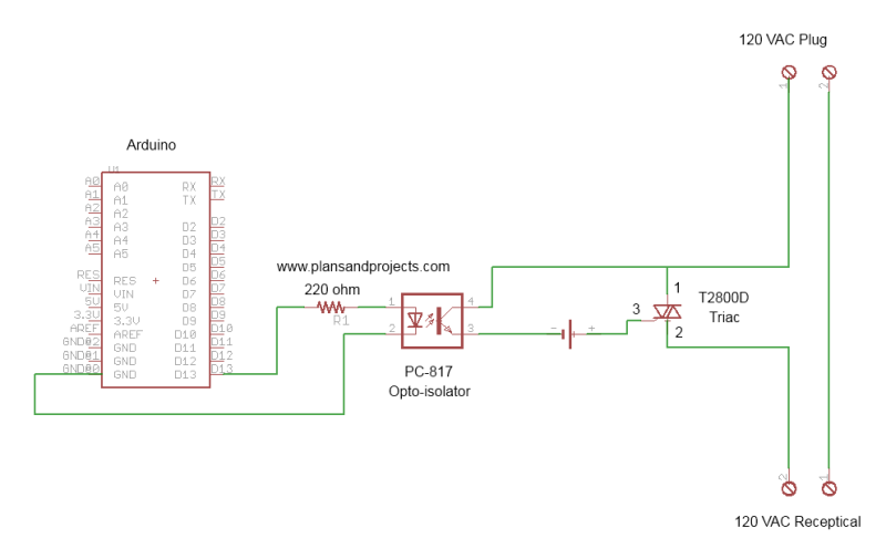 I used the blink sketch from the Arduino IDE examples. It blinks the built in LED on pin 13. So starting with pin 13, run a wire to your resistor. Connect the other side of the resistor to pin 1 of the PC-817. Pin 2 of the PC-817 connects to the ground of the arduino. Pin 4 of the PC-817 connects to pin 1 of the T2800D. Pin 3 (gate) of this device connects to the + battery terminal. The - battery terminal connects to pin 3 of the PC-817. I plugged a desk lamp into the receptical and it blinked in time with the LED on pin 13. If you want an inverted output, instead of connecting pin 2 of the PC-817 to ground, connect it to the +5V. Now the lamp will be on when the Led is off, and vice versa. There are many output pins on an Arduino, and many more on a Mega. There is no reason you couldn't duplicate this circuit on each one of them and control all kinds of stuff! Marquee signs, anyone? In the near future, I hope to use Pulse Width Modulation to regulate a cartridge heater using this circuit. |